Outreach Location Biogastur – 2018
26st and 27nd of September, a meeting was organized in the framework of the H2020 project SYSTEMIC, which aims to stimulate the implementation of sustainable and economically viable business cases for bio-waste, manure, sewage sludge treatment in Europe.
The meeting brought together representatives of 4 anaerobic digestion plants from different regions in Europe and the SYSTEMIC consortium.
The meeting took place in the meeting room “El Liceo” in Navia, Asturias, in the north of Spain, close to Biogastur, one of SYSTEMIC’s outreach locations.
To update the participating outreach locations on project results
- -To demonstrate the business development tool and start testing with it
- -Get their feedback on the tool
- -Visit the biogas plant of Biogastur
| Participant | Organisation/Company | Country | Function in SYSTEMIC |
| Andre Schelfhout
Patrick Schelfhout |
Biogas Bree | Belgium | Outreach Location |
| Michel Peter | SCRL Kessler | Belgium | |
| Tomislav Kitonic
Ante Topalovic |
Bojana | Croatia | |
| Rubén Wensell | Biogastur | Spain | |
| Oscar Schoumans | Wageningen University & Research | The Netherlands | Project Coordinator and WP5 leader of SYSTEMIC |
| Claudio Brienza | University of Ghent | Belgium | WP1 member of SYSTEMIC |
| Ludwig Hermann | Proman | Austria | WP2 leader SYSTEMIC |
| Marieke Verbeke | VCM | Belgium | WP3 leader SYSTEMIC |
| Lies Bamelis | DLV (Profex-United Experts) | Belgium | Subcontractor WP3 SYSTEMIC |
Welcome to Navia

Ignacio García Palacios, Mayor of Navia City Council (Spanish Socialist Workers Party)

Rubén Wensell, agricultural engineer and representative of Biogastur, Outreach Location
The SYSTEMIC consortium and outreach locations were warmly welcomed in the conference room of El liceo in Navia by the Mayor of Navia himself.
The mayor described the region of Navia as the region with the highest milk production in the North of Spain.
The region is also characterized by it’s agriculture, which is mainly corn, used as feed for the livestock.
In this region there are 134 dairy farms with each 200 cows, resulting in a density of 4 cows per ha and a manure surplus. Using the manure directly as fertilizer caused probles with nitrification of the groundwater. The mayor realized the importance of this issue for the region and was from the beginning very involved in the conception of the Biogastur-project.
This enormous biogas plant had the goal to treat 400.000 tonnes of cattle manure from the region with anaerobic digestion, hereby producing 30 GWel per year and the possibility to upgrade the biogas to biomethane to be used as vehicle fuel for cars and trucks. In full capacity the plants would produce 25.000 tonnes of dried solid fraction (80% DM), 350.000 tonnes of liquid fraction and 300 tonnes of struvite per year.
The mayor’s influence has undenyibly contributed to the succes of the Biogastur. The biogas plant is now running for a year, but at the moment only working on half capacity since it is still in start up phase. The mayor sees this project as 3 solutions for 1 manure problem:
- -The production biomethane as a green fuel for trucks.
- -The production of green electricity.
- -The creation of an environmentally safe fertilizer (digestate) that is low in nitrogen.
According to the farmers, who have been fertilizing their corn fields with the digestate, an increase the yield with 25% yield can be visually noticed. These numbers will be confirmed when the harvest is measured.
Visit to Biogastur Biogas Plant
Business Plan
The biogas plant is located in Navia in the province of Asturias in Spain and was started up in 2017 and is now running for a year.
The design of the plant and the business plan took nine years. Eventually the plant was built with 80 million € investments from 5 private investors and the milk cooperative (25%) and completely without any form of governmental subsidy. There is also no feed-in tariff for the produced electricity and gas.
The design of the plant and the business plan took nine years. Eventually the plant was built with 80 million € investments from 5 private investors and the milk cooperative a25%)(nd completely without any form of governmental subsidy. There is also no feed in tariff for the produced electricity and gas.
- Intake of the manure
- Electricity production and marketing on the grid
- Marketing the end products: dried solid fraction of digestate and liquid fraction of digestate
Each income contributes to ±30% of the incomes, so each income balances the others and the plant doesn’t depend on one income route completely, which makes it more resilient for changes in the market.
The business plan of Biogastur is quite unique in Europe and therefore it will be studied in detail by the SYSTEMIC project.
Feedstock
The plant has a total capacity to treat 400.000 tons per year.
350.000 tons per year consists of cattle slurry. Since the milk cooperative is one of the shareholders of the biogas plant, the manure supply is contractually established. When farmers cannot supply the amount of manure they promised, they pay a fine to make up for the income loss Biogastur suffers.
Biogastur has its own truck fleet with which they daily or weekly collect the cow manure from cattle farms in a radius of 50km. The furthest one is 70 km away, but this one is very large and only supplies once a week.
The milk cooperative (and thus the dairy farmers) are charged 2-2,5€/ton to treat their manure, including transport.
The milk cooperative also supplies 25.000 tons of dairy waste (spoiled milk, whey, etc.) per year.
Other waste streams (25.000 tons per year) that are digested are rabbit manure, rabbit slaughterhouse waste, flower, molasse and glycerin. Biogastur pays for the energy rich feedstocks, f.e. glycerin is 5 times more expensive than molasses.
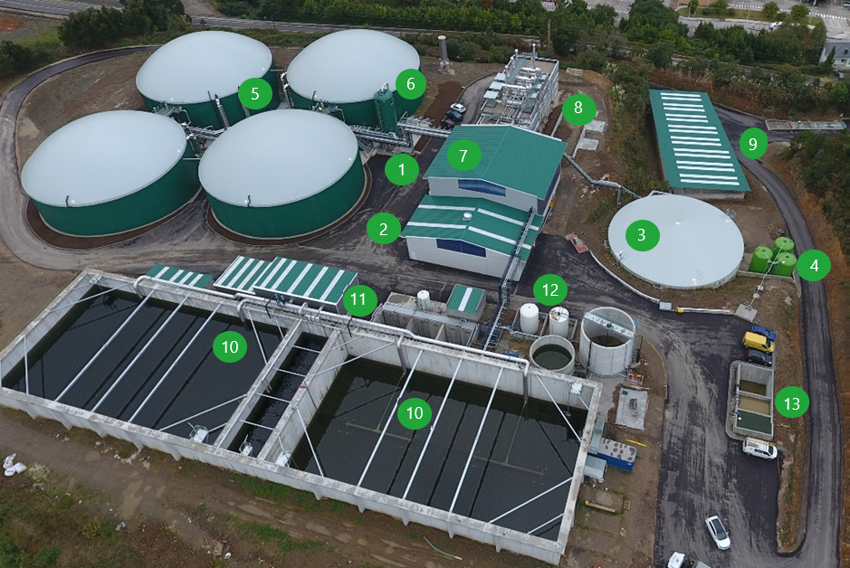
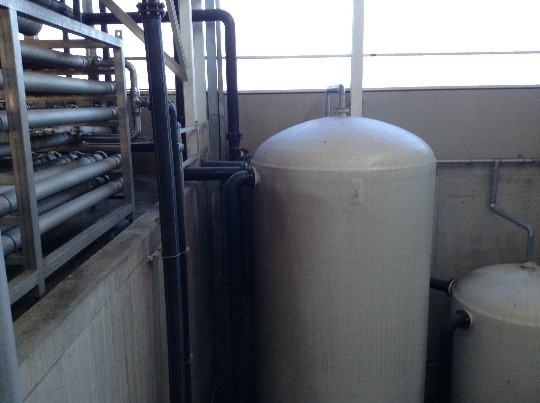
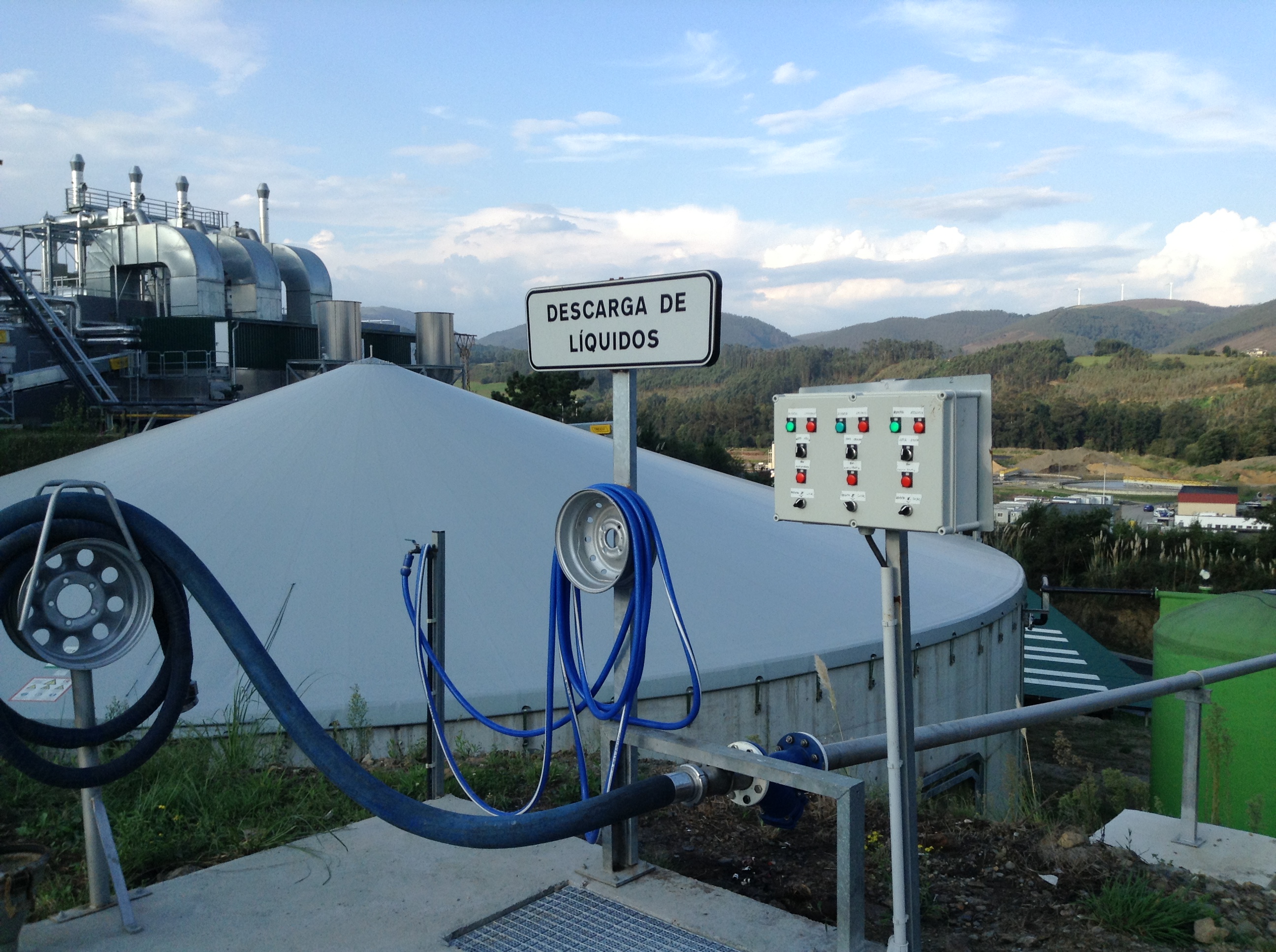
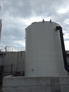
(2) in Figure 1 is the area where trucks with liquids can be washed and emptied. Residual heat from the CHP is used to heat up a water boiler (Figure 3) and warm water is used to clean the trucks.
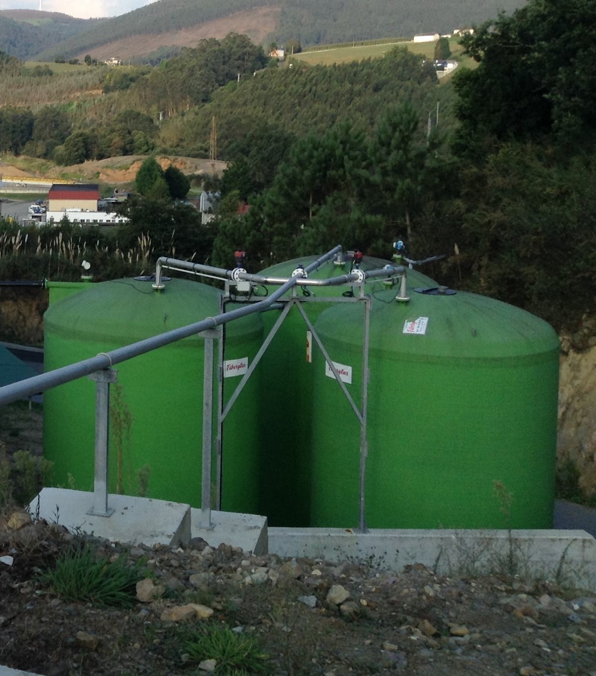
(1) in Figure 1 has a special reception unit for solid waste. (3) shows the mixing tank for solid waste and manure, (4) are 3 tanks of each 60m³ for liquid wastes (glycerin, molasse, whey, spoiled milk). The mixing tank is 3000m³ and has 3 days buffer capacity. It can also serve as quarantine. The mixing tank mixes the solid waste with liquids to a DM content of 8%, approximately. This mixture is pumped to the digesters.
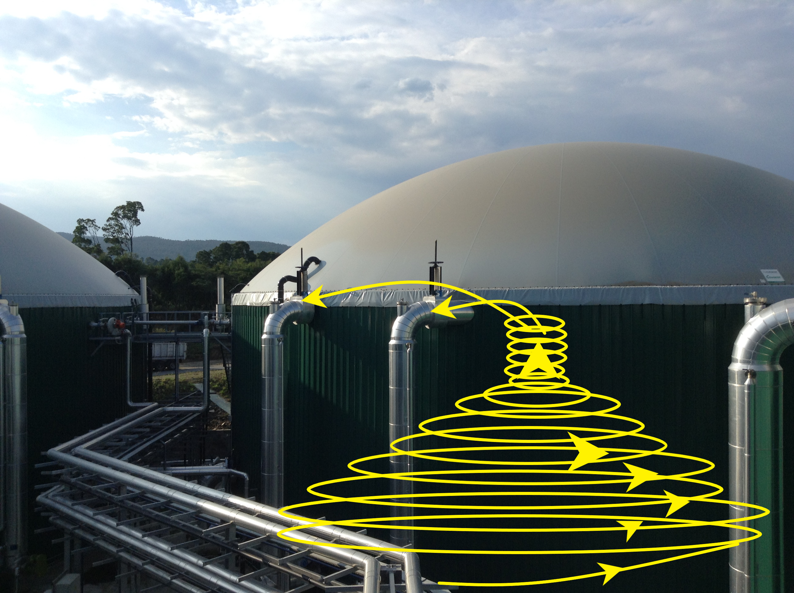
The biogas plant has 4 thermophilic digesters of each 7000 m³ (5 in Figure 1). Each digester has 3 recirculation pipes, and one of them also is a feeding pipe. This last one feeds pre-heated feedstock at the bottom, pumping it in a circular movement around the digester. At the same time, the three pipes suck up digestate from the top in the middle of the digester and inject it again at the bottom parallel to the walls of the digester. This creates a vortex moment in the digester which mixes the digestate and feedstock and realized optimal biogas production (Figure 5). The residence time is 3 to 4 weeks.
Sometimes flour is used as a feedstock. Instead of mixing this in the mixing tank, this is carefully injected directly in the digesters in very small volumes, to not influence the dry matter content to drastically, since the viscosity of the digestate in the digester determines how easy biogas is created and can escape the slurry.
Since it concerns thermophilic digestion, which is more sensitive than mesophilic digestion, the input loading rate is since the start-up increased very slowly to guarantee the adaptation of the bacteria from mesophilic to thermophilic. This is also the main reason the plant only runs on half capacity at the moment. All 4 digesters digesters are being used but the content is transferred from one to the other as needed in the preliminary tests and essays.
Biogas and heat
Yearly 17.000.000Nm³ of biogas is produced.
The biogas is scrubbed (6 in Figure 1) to remove the hydrogen sulfide (H2S) to <1000 mg /L, to guarantee the efficiency of the CHP engine and prevent corrosion damage to it. The removal of H2S efficiently facilitates the upgrade of biogas to natural gas quality.
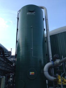
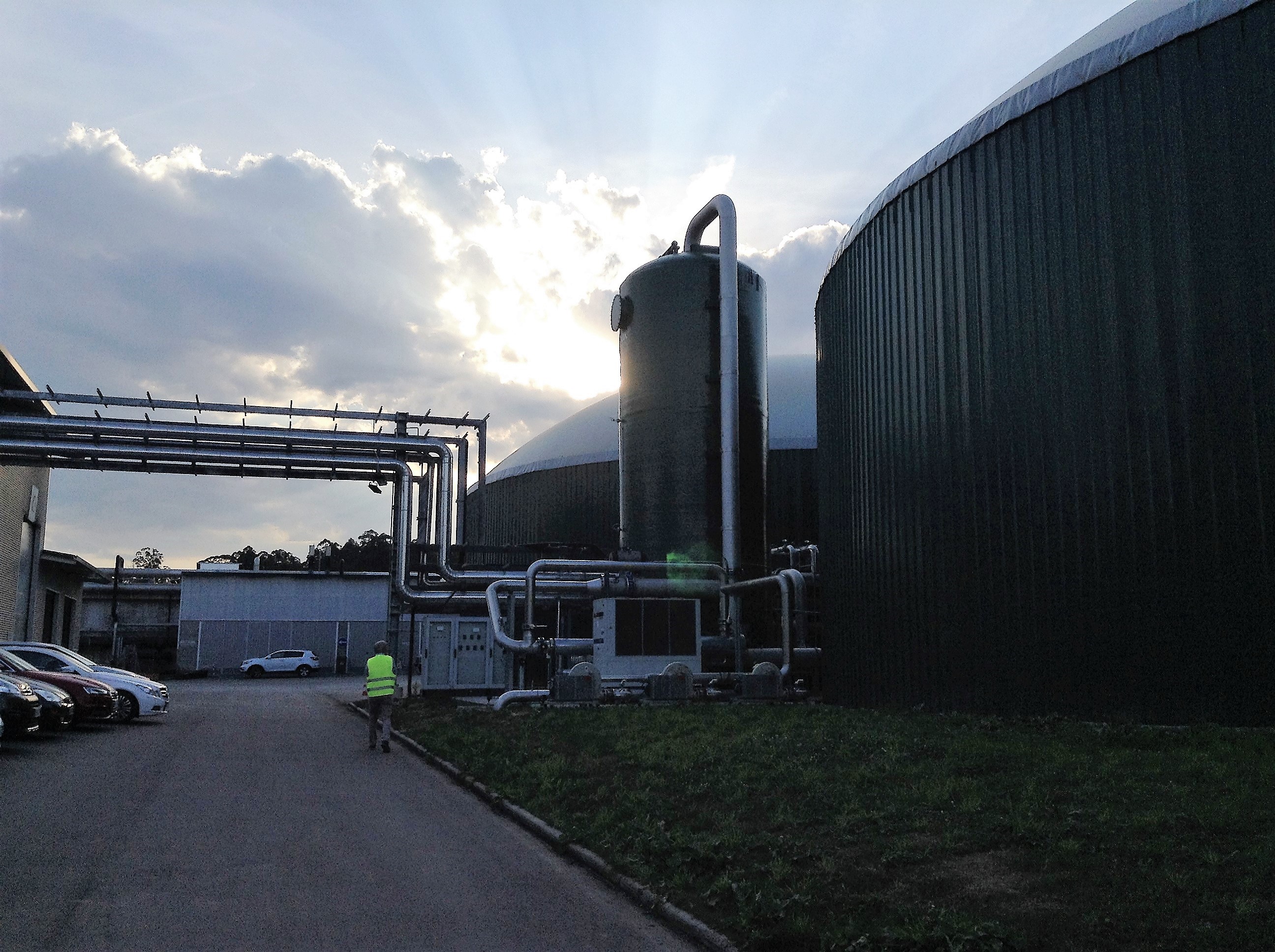
Biogastur works with a patented system based on a biological desulfurization tower: the BIDOX® system (BIological Desulphurization by OXidation) (Figure 6). Biogas desulphurisation using the BIDOX is not associated with odour emission, because the system is completely closed. In addition there is no need for internal cleaning or biomass discharge or adding chemicals.
The BIDOX represents a fully automated and biological system in which biogas is treated in counter flow with washing water. During this treatment aerobic bacteria attached to the packing material inside the BIDOX convert H2S in the biogas almost entirely into sulphate.
To do this, the bacteria require oxygen. Therefore, 20% of the volume of the biogas is added in O2. The resulting methane concentration is around 64%.
The sulphate is discharged with the BIDOX effluent in the form of very diluted sulphuric acid. The sulphuric acid is discharged via the aerobic purification (MBR) installation (see later), where it is used as a nutrient and improves the buffer capacity.
The exploitation costs for the installation are low when compared to other biogas desulphurisation technologies. The power consumption of the BIDOX system is in the order of 0,21 kWh/kg H2S removed and the combined operational and maintenance costs mount up to around 0,10 -0,25 € / kg H2S removed. The majority of the maintenance costs are associated with the calibration of the measurement systems.
Process obstruction as a result of sulphur precipitation or foaming are not observed as a result of the low pH. For more information visit the Colsen website.
The biogas is valorised in to 30 GWh of electrical energy per year by means of in 3 Jenbacher 420 CHP engines (7) of each 1,5MW with and electrical efficiency of 42% and a thermal efficiency of 44%.
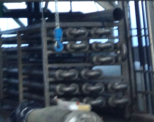
The heat from the CHP, hot water, hot air and flu gasses are recovered as 4,692 kWth and this is used to heat up the feedstock (by means of a heat exchanger, Figure 7), the belt dryer and water in a water boiler for internal cleaning (Figure 3) and the dryer. All the heat is used for warming up the total raw materials received, as for the thermophilic process they have to increase their temperature up to 52-55ºC and also for the belt dryer.
Part of the electricity is used on the site and the rest is sold to the electricity distributor at market prices (highest price in October 2018 was 75€/MW).
Biogastur is looking into upgrading the biogas to liquified biogas (LBG) to use as fuel for their truck fleet. To develop this technology, Biogastur has signed a plan with the national leader in gas distribution, ENAGAS, which will invest around 1,2 M€ in the upgrading technology and the connection to the national grid. The biomethane will be enriched from the starting point of 60-65 % up to the 95-98% of methane, required for the national grid.
Separation of the digestate
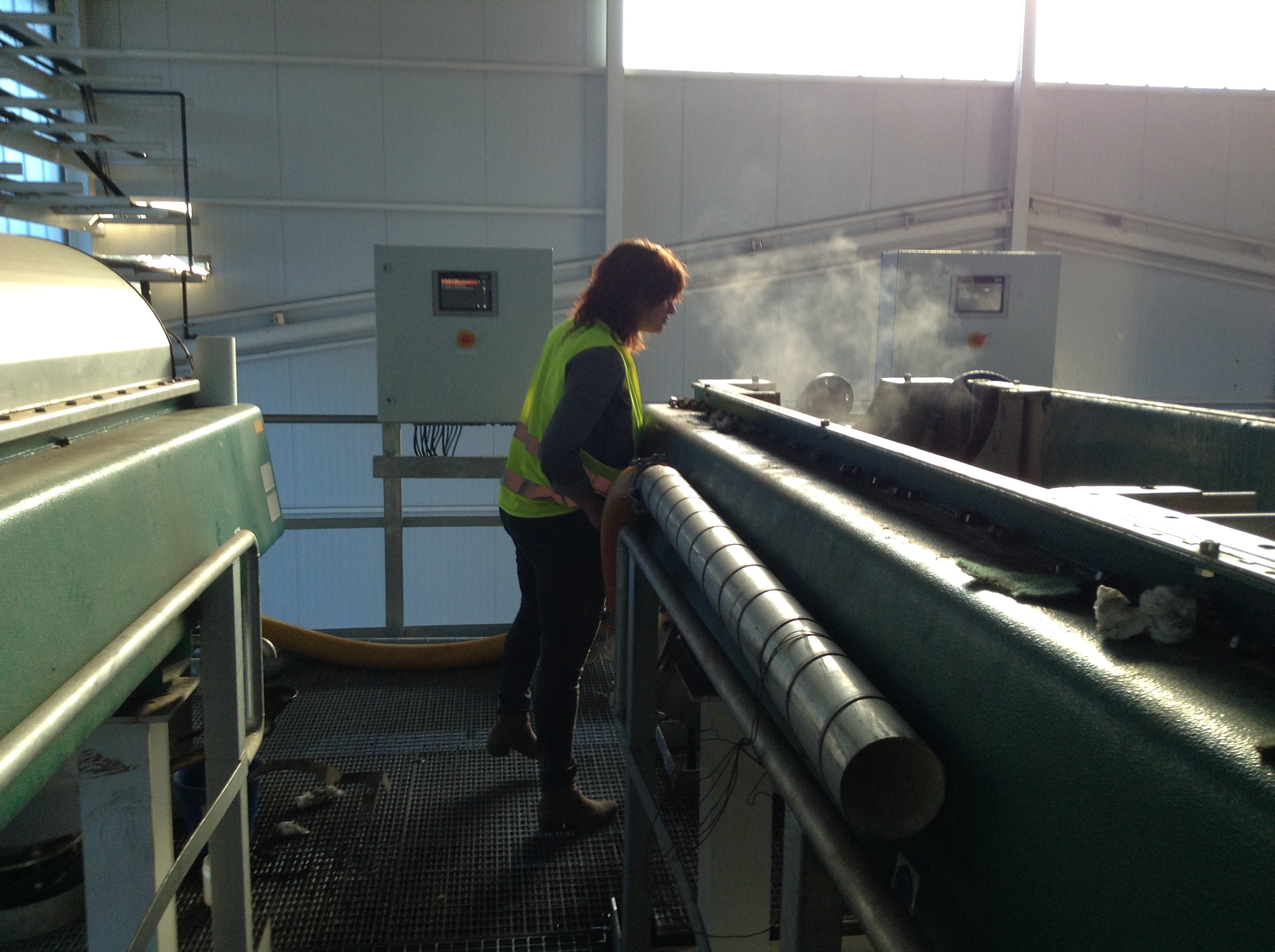
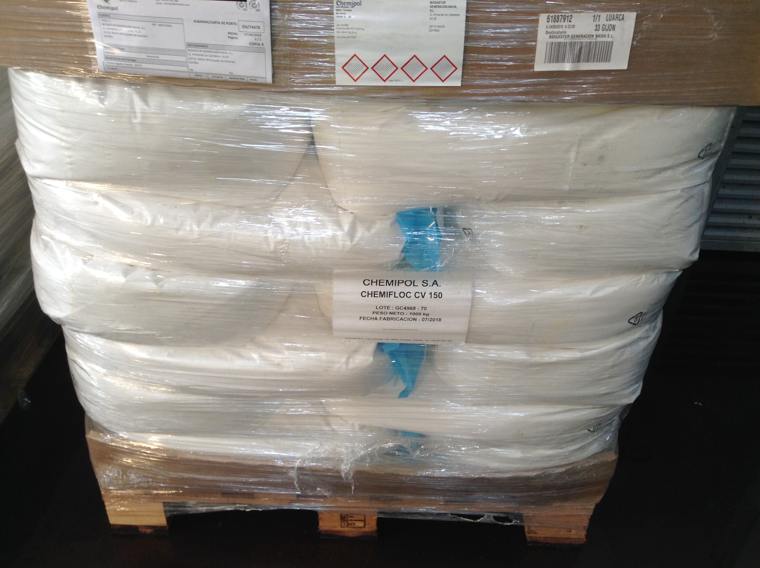
After anaerobic digestion, the digestate (350.000 tons per year) is separated by means of 2 centrifuges (Figure 8). To improve the separation efficiency several polymers are used, depending on the temperature, the pH, the solids concentration, and so on. Figure 9 shows a picture of one of the powder polymer (CV 150, CV 300) is added.
A curious fact was that there was almost no smell of ammonia in the neighborhood of the centrifuges. This suggests an air cleaning treatment step before the separation step (see further).
Drying of solid fraction
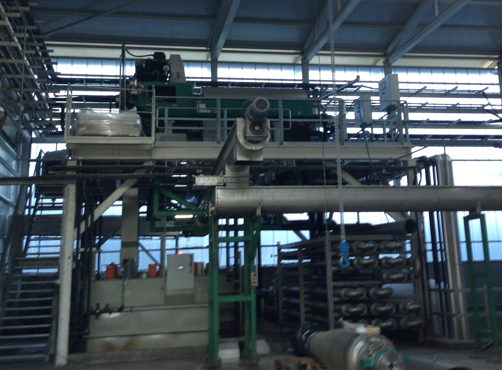
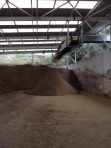
In (8) of Figure 1 the dryer is located. This is a belt dryer which dries with recovered heat of the CHP the solid fraction to 75-90% dry matter content. 10.000 tonnes of water per year is evaporated and the solid fraction is stored in a warehouse (9). Biogastur sells this to farmers as fertilizer with their own (precision) spreading equipment for a fixed price.
Now, during the start-up, the dried product is often offered for free to farmers as trial, but once the plant will be running on full scale a price will be asked for the solid fertilizer + application. The microbiological analyses on a mix of ashes with dry fraction and sawdust done have proven to contain halve the amount of E. Coli, Streptococcus, enterobacteria and other colonies ,compared to the cow bedding done with sand and calcium carbonate.
Air cleaning system
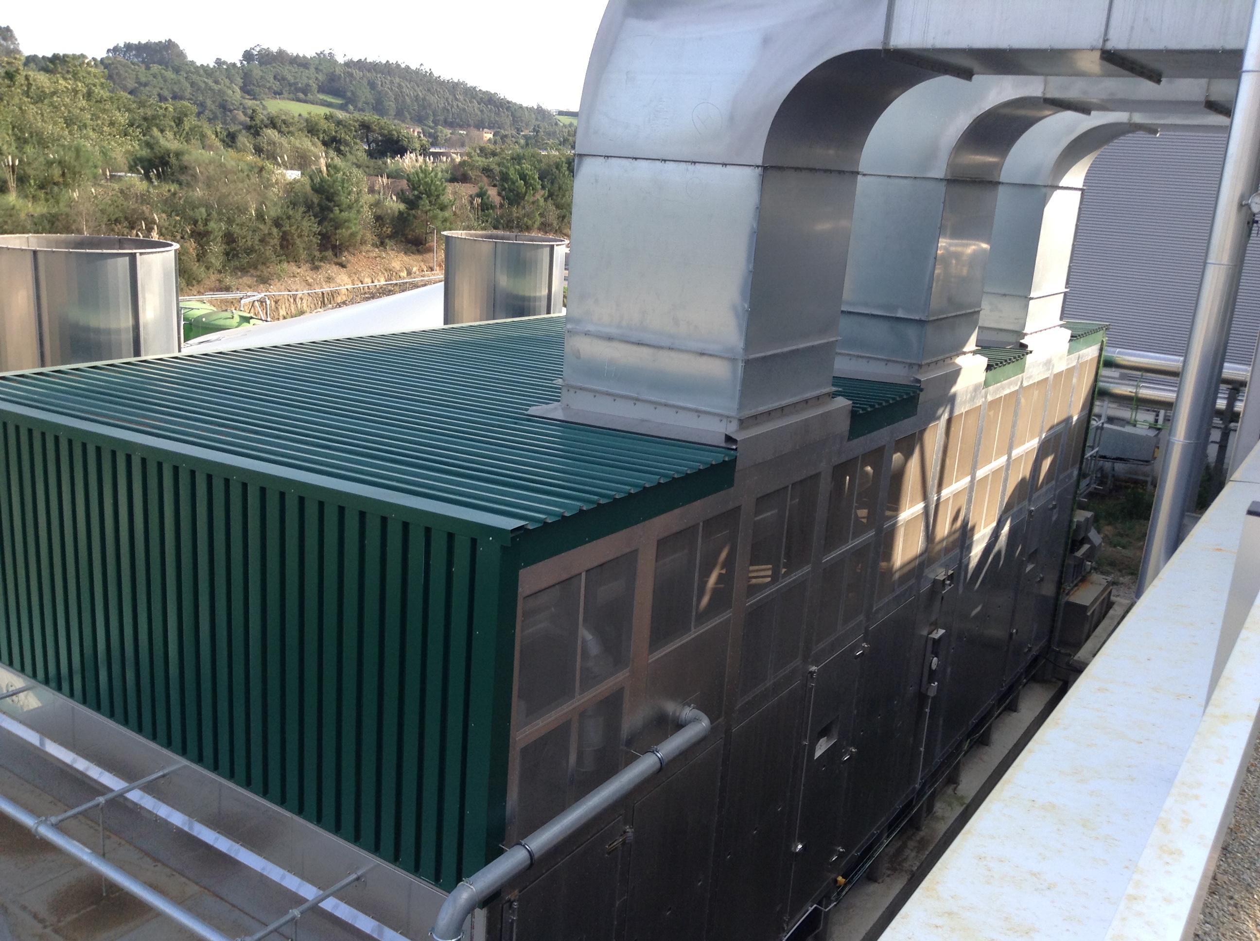
Again, no smell was noticeable at the dryer or the exhaust pipes, yet there was no air washing system nor biobed visible.
The air cleaning system appeared to be also patented and therefore no more details about the mechanism could be revealed. The system proved to be very effective, and the environmental permits were obtained by only limited description of the mechanism, and its efficacy substantiated with emission measurements.
This led to a lot of speculation amongst the visiting Outreach Locations and project partners.
Since there was no smell during separation, it was suggested that the air cleaning should be located somewhere in the digester or on the raw digestate.
Also no chemicals (acids) were noticed on site, which suggested that air scrubbing with acid was not done here. The fact that ammonium sulphate is subject to REACH regulation in Spain, reinforces this hypothesis.
Somehow the ammonia is removed from the digestate and most likely, the liquid ammonia solution is biologically treated in the MBR-NAS.
Nonetheless, we have no confirmation of these speculations and therefore the air cleaning mechanism and technology remains a secret.
Nitrification-denitrification of the liquid fraction
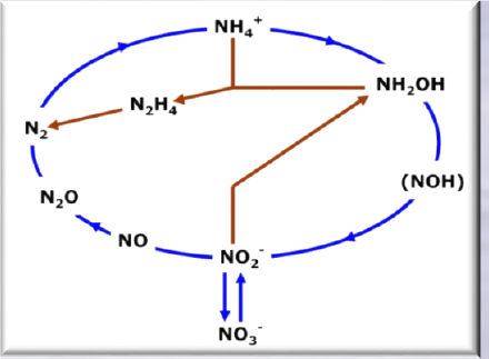
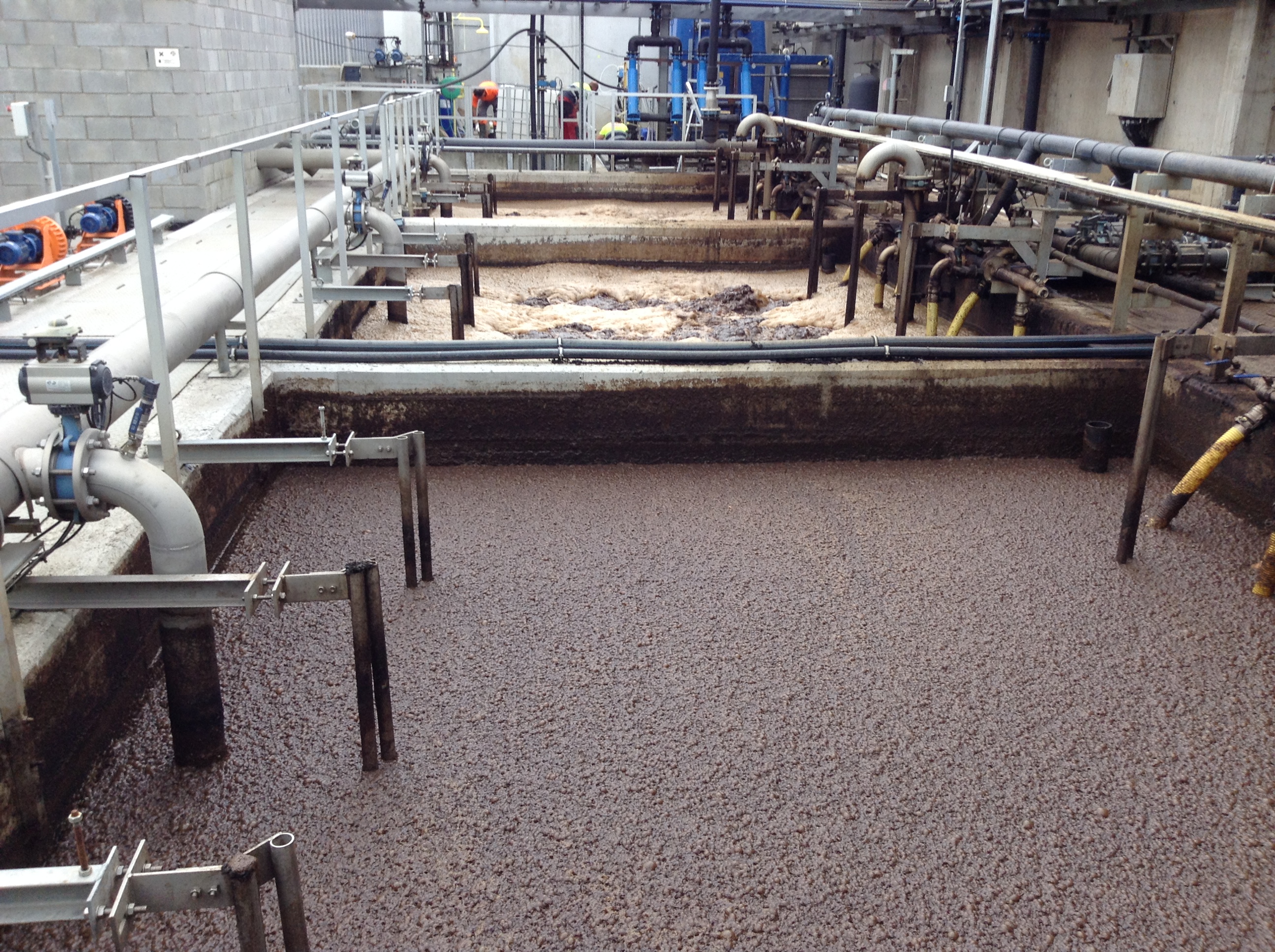
350.000 tons of liquid fraction per year is produced by the centrifuge. This goes to a NAS® (New Activated Sludge) system in 2 aeration basins (10) in which air is blown. The basins contain an activated sludge in which anammox bacteria constitute a part of the biomass (Figure 11).
In the first aerobic tank, a part of the ammonium nitrogen (NH4-N) is mainly oxidized to nitrite and partly to nitrate. In the next anoxic compartment, the nitrite and nitrate are denitrified. At the same time they convert COD into CO2 and biomass. Part of the remaining nitrite and NH4-N is converted directly into nitrogen gas by autotrophic organisms (Annamox, red arrows in Figure 11), under exclusion of oxygen and without conversion of COD. The remaining nitrogen is oxidized to nitrate in the 2nd aerated compartment. This nitrate is further denitrified during internal circulation.
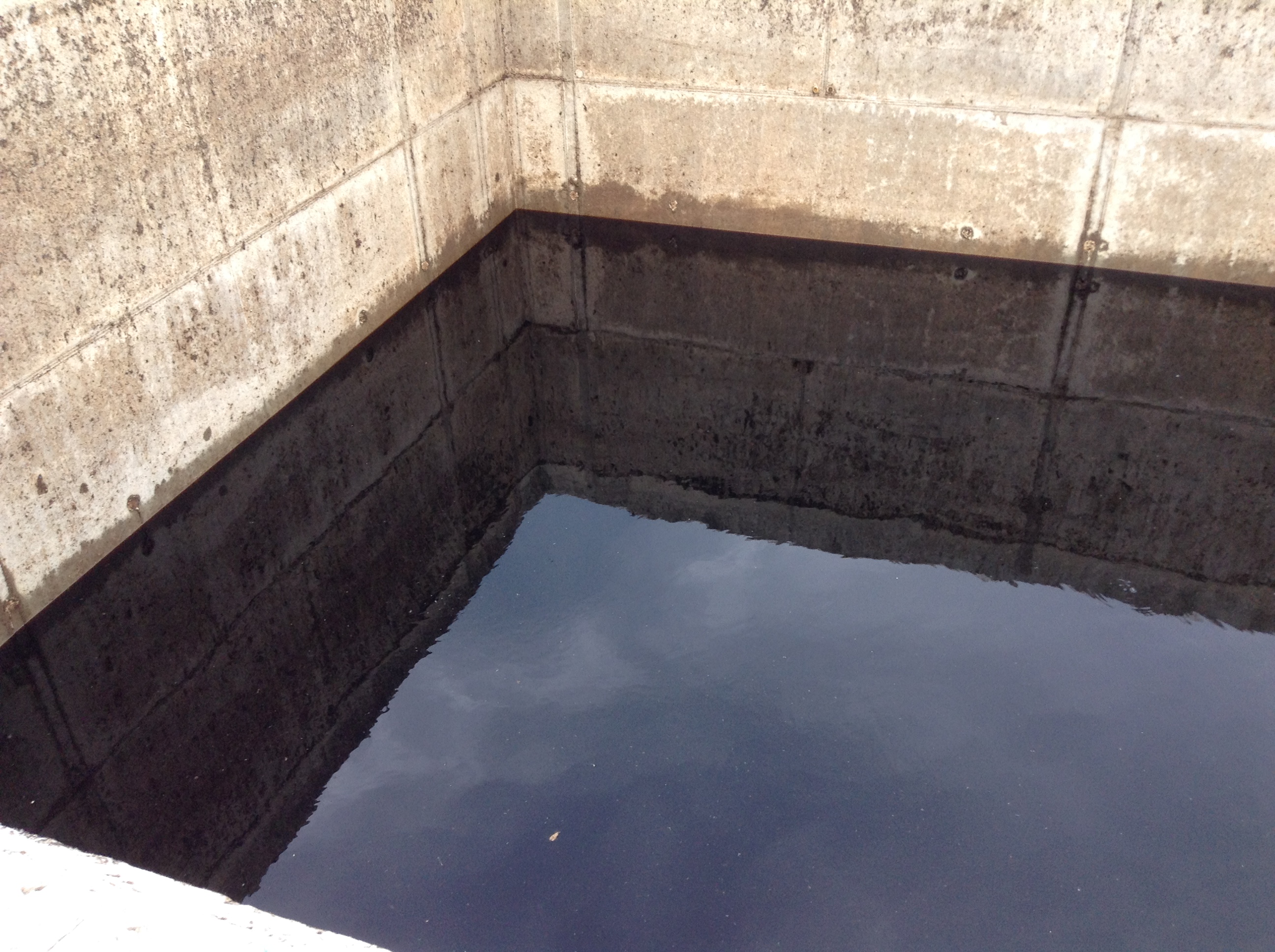
The activated sludge, which contains the bacteria, is separated from the effluent by means of ultrafiltration membranes (MBR) (11). The effluent (13) contains 200 mg N/L and Spanish discharge limits allow this to be discharged together with the purified wastewater of the paper factory (100 x dilution) in the sea. The effluent can also be used as liquid fertilizer for corn and other local crops, including municipal parks and golf courses.
Phosphorus recovery
The plant has and ANPHOS® reactor (patented) to recover phosphorus from the NAS®effluent. During the previous treatment step, the phosphate present is largely converted into ortho-phosphate with potassium as counter-ion.
The basic principle of the ANPHOS® process is the aeration of the NAS®effluent, which induces a positive pH shift. As a result of the addition of magnesium(hydr)oxide, the ortho-phosphate reacts with ammonia and magnesium ions to form magnesium-ammonium-phosphate (MgAP) or magnesium-potassium-phosphate (MgKP) also known as ‘struvite’. After the reaction, the struvite is precipitated, dewatered and dried and can directly be applied as substitute for agricultural fertilizers.
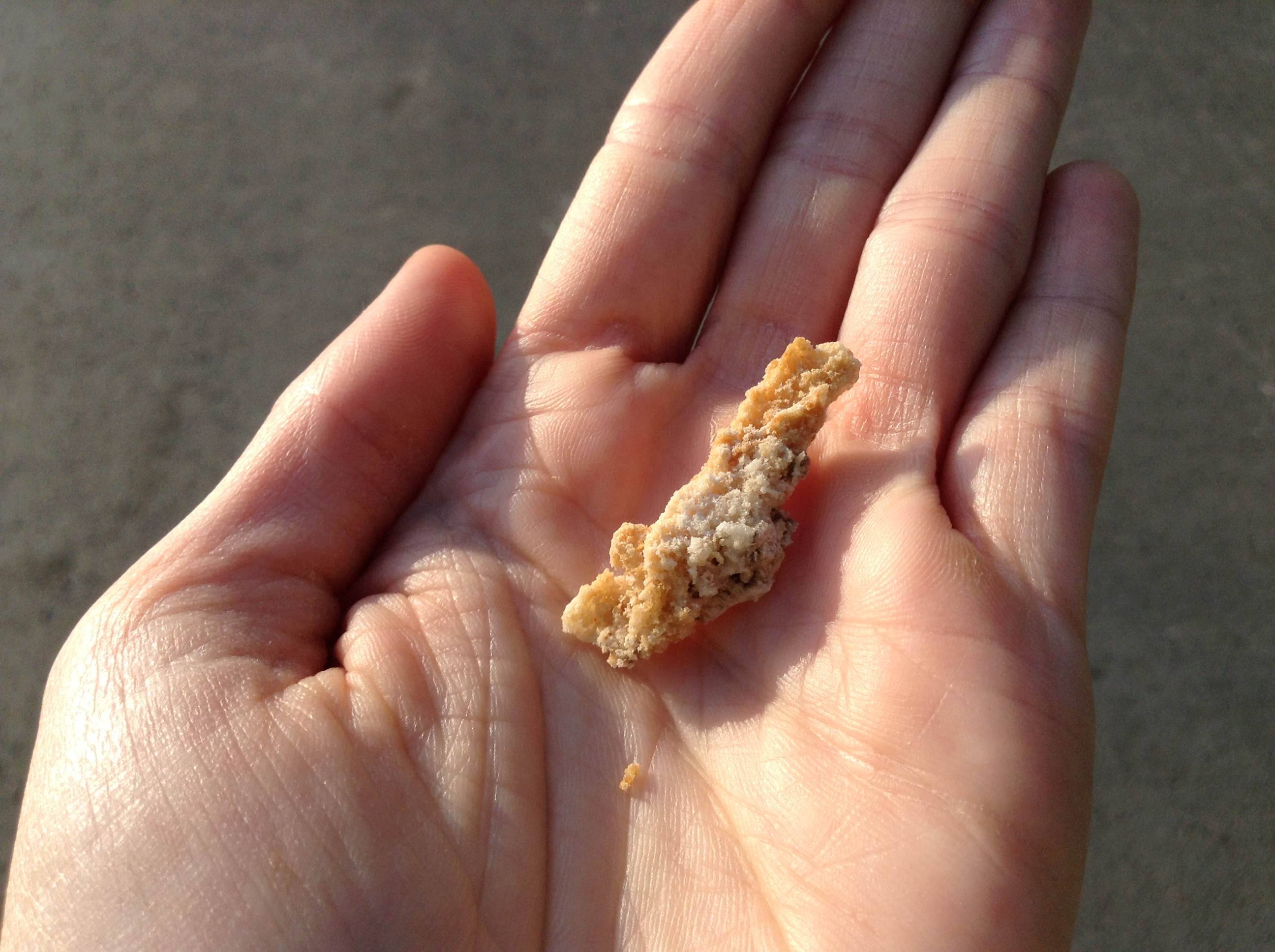
There are some small deposits of struvite in the pipes near the centrifuges, which proves that struvite precipitation is technically possible.
Yet, because the biogas plant is currently not yet running on full capacity, there is not enough phosphorus in the effluent (average 177mg P/L) to precipitate large volumes of struvite. Which means that at the moment it is not yet profitable to recovery phosphorus from the effluent.
It is estimated that the plant could produce at maximum capacity 1 tonne of struvite per day. A few years ago, about 1100 €/tonne struvite was a realistic market price. If a lower price is offered, there is still an option to blend the struvite with the solid fraction and sell it as complete P-organic matter blend.
Conclusions and feedback
As far as biogas concerns, Spain is a market that is still has to be developed, and more specifically to agro-industrial biogas. In this sector, Biogastur we will be market leaders on the level of energy production (whether as biogas or such as electricity), the technologies implemented and the level of management of waste and GHG reduction (34,000 tonnes equivalent annual CO2).
The outreach locations and consortium members were impressed by the plant and especially the business case running without subsidies.
The patented air cleaning system impressed and frustrated everyone, because the working mechanism remained secret.
Yet, some critical remarks can be made.
The composition of the effluent after NAS® (200ppm N) is extremely high in comparison to the discharge limits in other European countries (f.e. 15 ppm in Belgium for surface water).
One does need to mention that Biogastur’s effluent is discharged in the sea and not in surface water and that the effluent is first diluted (factor 100) with treated wastewater from the paper factory.
Nonetheless, in most European countries, dilution is not regarded as a waste treatment step.
Also, the plant does not recover any nutrients (yet). All nitrogen is lost as N2 and because of the REACH obligation for ammonium sulphate, N recovery by means of stripping-scrubbing is no obvious alternative. On the other hand, other markets for ammonium sulphate, -nitrate of ammonium solution could be researched (cfr. Industrie, paper factory?) to also valorize this nutrient.
Yet, Biogastur wants to wait and see how the demand evolves for liquid fraction or NAS-effluent as a fertiliser. If this is positive, they will discharge less into the sea and give or sell more to local farmers.
Also have questions or remarks on the plant of Biogastur? Let us know in the comments section below.





Leave a Reply
Want to join the discussion?Feel free to contribute!